8 Pin Relay Circuit Diagram
8 pin relay diagram you are welcome to our site this is images about 8 pin relay diagram posted by ella brouillard in 8 category on may 09 2019. It can be used for various switching.

Omron Mk2p S Wiring Diagram Sample
1) position the multimeter in the ohms range, preferably in the 1k range.

8 pin relay circuit diagram. Eaton wiring manual 0611 5 6 5 5 circuit diagram load current and voltage responses protected against polarity reversal also for ac additional drop out delay induction voltage limiting defined. In the next section, a demonstration on identifying the pins of a relay from spdt or dpdt type without referring to its datasheet will be illustrated. Relay 8 pin diagram engine wiring diagram images, latching relay circuit schematic azatrax com, amazon com enclosed power relay 8 pin 120vac dpdt, omron plug in relay 8 pins square 120vac ly2 ac110 120, 120 volt relay wiring best free wiring diagram, 2 pole 8 pin relay pinout diagram jacob in 2019 wire, omron 14 pin relay mscdirect 2 / 10
The polarity of the voltage does not matter. See my switch terminology page for more on contact arrangements if you need to. However, this article will explain everything you need to know about this topic.
The diode prevents relay from arcing by giving a return path for the energy stored in the magnetic. Since the normally closed contact is empty, the led is off when there is no voltage at the relay coil ends. 8 pin timer relay wiring diagram
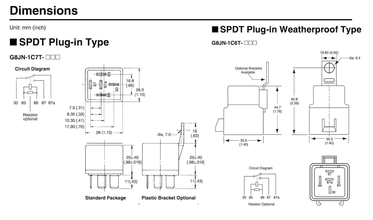
Basic schematic circuit diagram of relay. The diagram above is the 5 pin relay wiring diagram. In order to know how to connect a dpdt relay, you must know what each pin terminal represents and how the relay works.
Relay can be the best option to control electrical devices automatically. Connect the relay with hc11 port pins this is used to control on switches. With such an illustrative guide, you’ll be capable of troubleshoot, stop, and complete your tasks easily.
Additionally, all eight relays share a similar electronic circuit design. Run a wire from the n/o terminal on the limit switch to pin #7 on the relay (other side of coil) run the load from the motor through pins 1 and 5 (n/o) on the relay. Using a 4 pin relay for our example, we must first identify the pins.
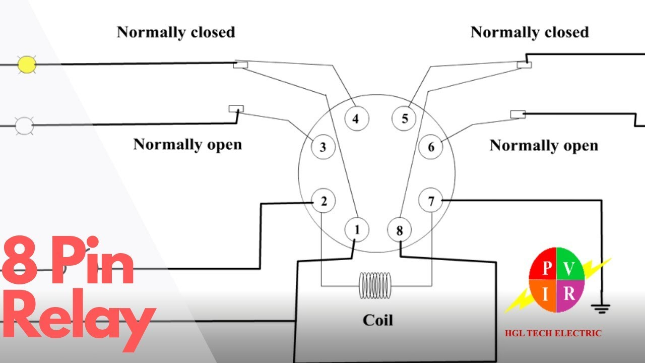
Some manufacturers place a diagram and pin id on the outside of the relay case to show which pins are part of the control circuit and which pins are part of the load circuit. Place the relay's rated coil voltage on these terminals. This is the diagram below to learn all the pin terminals of a double pole double throw (dpdt) relay:
What is an 8 channel relay module? It shows the components of the circuit as simplified shapes as well as the power and also signal connections in between the gadgets. Ladder and wiring diagram using an 8 pin electrical relay to turn on and off lights.
The relay works on the principle of electromagnetic force when the coil is energized it becomes magnetized in an 8 pin relay as shown here there are 2 common contacts 2 normally open contacts and 2 normally closed contacts relays control one electrical circuit by opening and closing contacts in another circuit. Pin's 8 & 6 as normally open pin's 8 & 5 as normally closed. Proper way of wiring 8pin 120ac volts coil relay.
This diagram will show you how simple it is to control motors, lights, valves, other relays and any type. 8 pin timer relay wiring diagram electrical and electronics technology degree. Relays that normally used in electronic circuits are spdt and dpdt types due to their flexibility in controlling circuit switching.
5 pin is compromised of 3 main. In this diagram, eight separate loads (represented by lightbulbs) have been connected to the no terminals of the relay. When the relays are activated,.
In this article, we go over how to connect a double pole double throw (dpdt) relay in a circuit. How to connect a dpdt relay in a circuit. The 2 coil terminals is where the voltage is placed in order to energize the coil.
Run a neutral wire to pin 8 (one side of the relay coil) run a hot wire to the common on the limit switch. There are different kinds of relays for different purposes. 2) begin by connecting the meter prods to any of the two pins of the relay randomly, until you find the pins which indicate some kind of resistance on th meter display.
Combination boiler with 2 heating zones relay switching. Club car turn signal wiring diagram diagram turn ons electrical circuit diagram. With the circuit shown in figure 1.7, led1 can be switched off by relay and button control.
The blue path can not be used. The transistor allows the hc11 to control the medium sized coil current of relay. Utility trailer wiring diagram best of trailer wiring diagram air brake brake system.
A double pole double throw relay comes with 8 terminal points. A wiring diagram is a simple visual representation with the physical connections and physical layout of your electrical system or circuit. In addition, these are also widely used to switch starting coils, heating elements, pilot lights and audible alarms.
The live wire has been connected to the common terminal of each relay. By looking at the diagram below we can go through the basic concept of a relay and how they operate. Protective relays can prevent equipment damage by detecting electrical abnormalities, including overcurrent, undercurrent, overloads and reverse currents.
Relays are easy to test but often misunderstood. Not merely will it help you attain your desired results quicker, but also make the complete procedure less difficult for everybody. The identification of a typical relays pinouts may be done in the following manner:
Relay wiring diagram 8 pin ice cube with switch circuit for motor. They permit a small circuit to manage a far along flow circuit using an electromagnet to manage the flow of electricity inside the circuit. How to wire a relay 8 pin timer wiring diagram heating zones switching connection of ac control ssr connect dpdt in circuit 220vac 5a terminals please help with the 230v.
It contains instructions and diagrams for various kinds of wiring strategies along with other items like lights, windows, and so forth. The following schematic shows the basic circuit. 60 luxury 8 pin relay wiring diagram pdf relay electronic parts electromagnet

8 pin relay wiring diagram Wiring Diagram and Schematic

8 Pin Relay Wiring Relay With Base Connection How
24v 8 Pin Relay Wiring Diagram Diagram Media

50 Luxury 5 Blade Relay Wiring Diagram Electronic

8 Pin Relay Circuit Diagram Diagram Media

5 Pin Relay Wiring Diagram Use Of Relay

8 pin relay wiring. Relay connection. 8 pin relay

Spotlight Wiring Diagram 5 Pin Relay Wiring Diagram

14 Pin Relay Wiring Diagram Blog Selector

8 Pin Relay Wiring Diagram Wiring Diagram
8 Pin Ice Cube Relay Wiring Diagram
Omron 8 Pin Relay Wiring Diagram Collection

Cube With An 8 Pin Relay Wiring Diagrams diagram wiring

Wiring Diagram For 6 Pin Relay
Relay Wiring Diagram 8 Pin WIRGRAM

4 Pin Relay Diagram 12 Volt Car Relays Used In

8 Pin Relay Ladder Diagram Electrical circuit diagram


